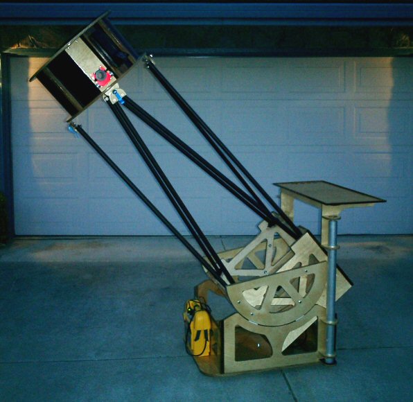
Construction DetailsI began designing the telescope on March 30th, 2004 and began construction on April 9th, 2004. The total construction took a little over 300 hours over a 10 week period. The design changed several times during construction to deal with various issues that came up. Since the goal was to take the scope to the Shingletown Star Party, schedule took precedence over optimal design at several points during the construction. For example the original plan was to use a low profile, small mirror cell, but because of delays in shipment I ended up going with the mirror cell/sling from the original dob. This resulted in the mirror box being larger than I originally intended. There were also problems related to the secondary size and the truss clamps. Details can be found on the Construction Diary page.
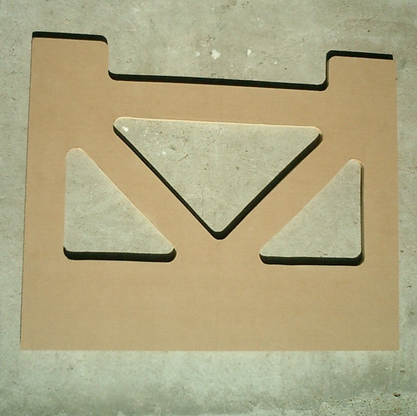
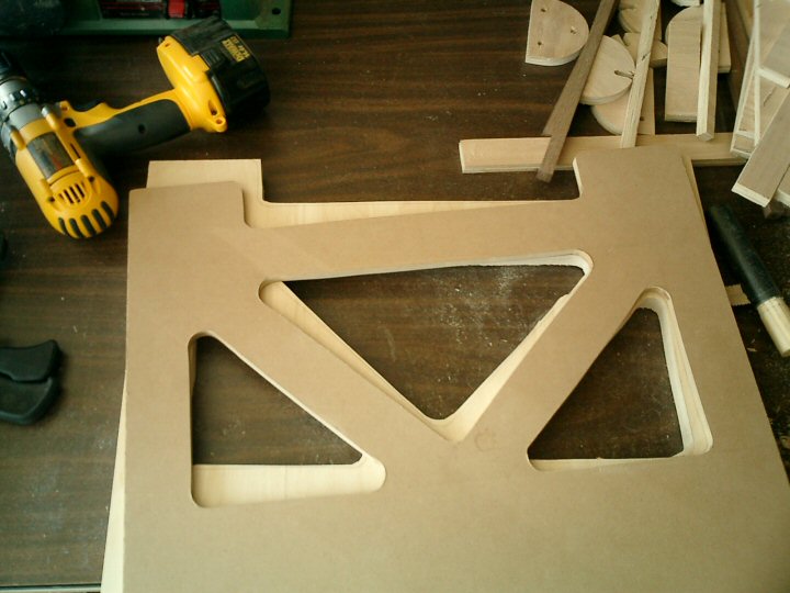
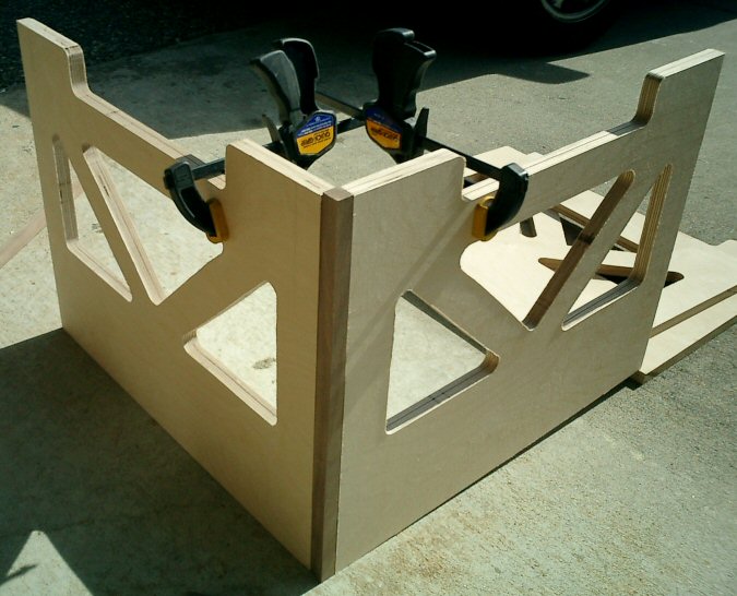
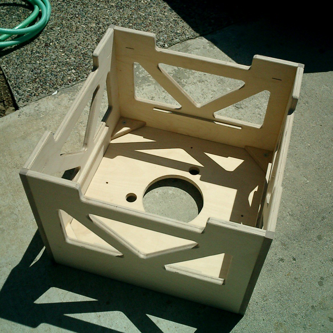
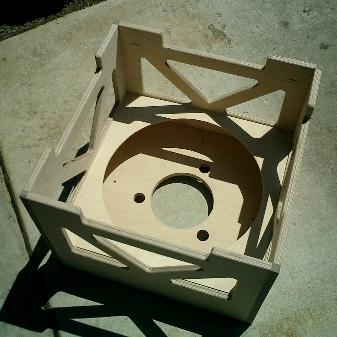
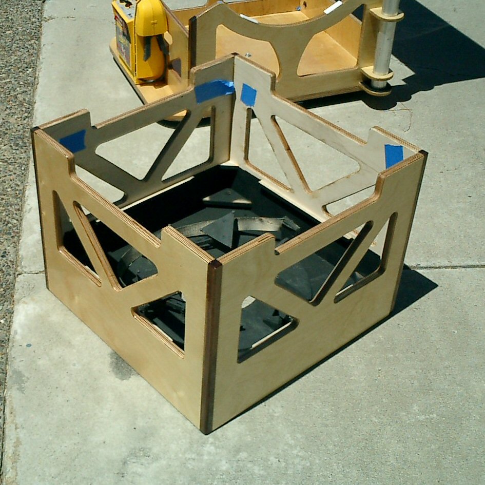
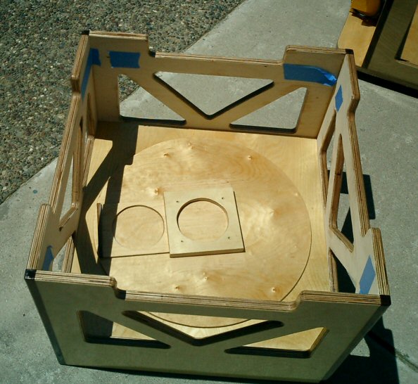
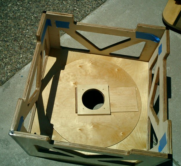
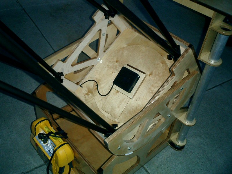
Mirror BoxThe mirror box is constructed using 3/4″ Finnish Birch. The corner joints are 3/4″ walnut strips that are glued into the corners using biscuit joints. To reduce weight I made a template and routed out sections of the side as shown below. The mirror cell is attached to a piece of 3/4″ Finnish Birch that is bolted into the bottom of the mirror box. This allows me to remove the mirror and mirror cell. The plan is to replace this mirror cell with a lower weight mirror cell down the road so this was a way to be able to easily change the mounting for the new mirror cell.
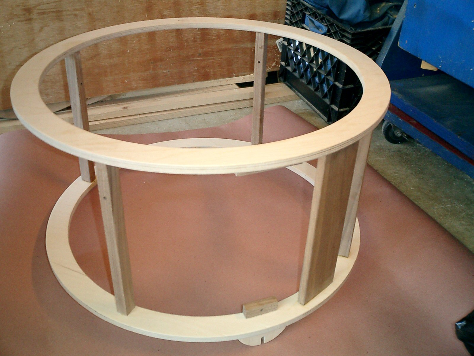
Upper Tube AssemblyThe upper rings are constructed using 1/2″ Finnish Birch and walnut strips to connect the two rings together.The finder board is 1/2″ thick walnut. All of this was glued together to form a solid structure. The focuser board was bolted to the ring so that I could change it down the road if I decided to use a different type of focuser. I didn’t want to cut out a piece of glued board. On the bottom edge of the ring I glued for wood supports that are used to clamp to the truss tube clamps.
Rocker BoxThere were several design goals for the rocker box
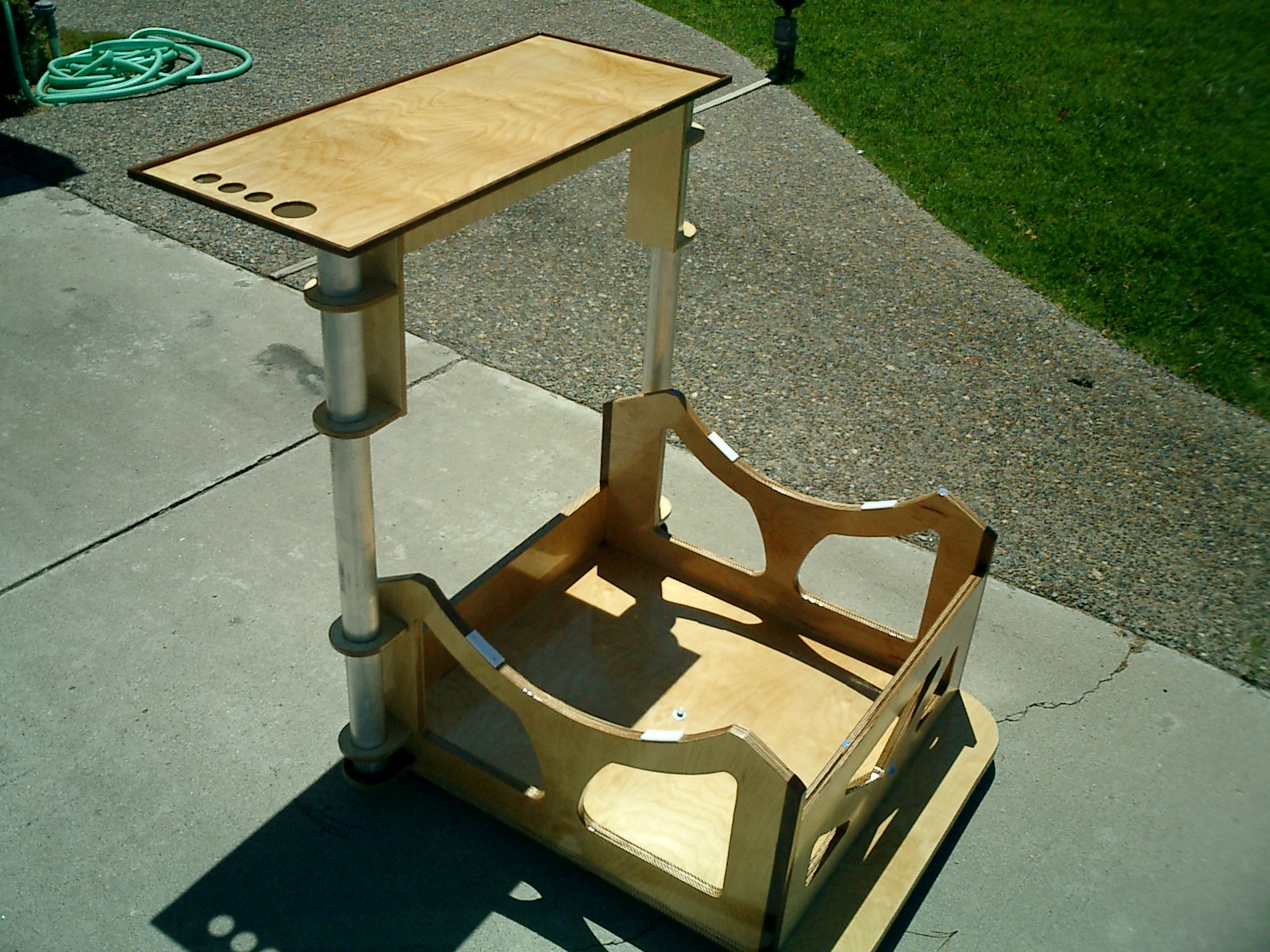
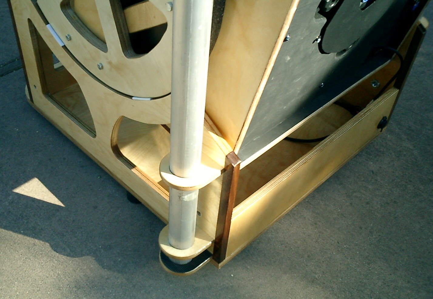
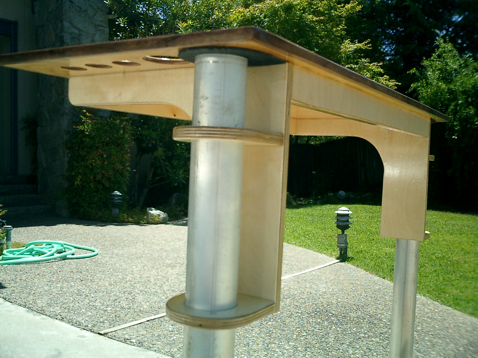
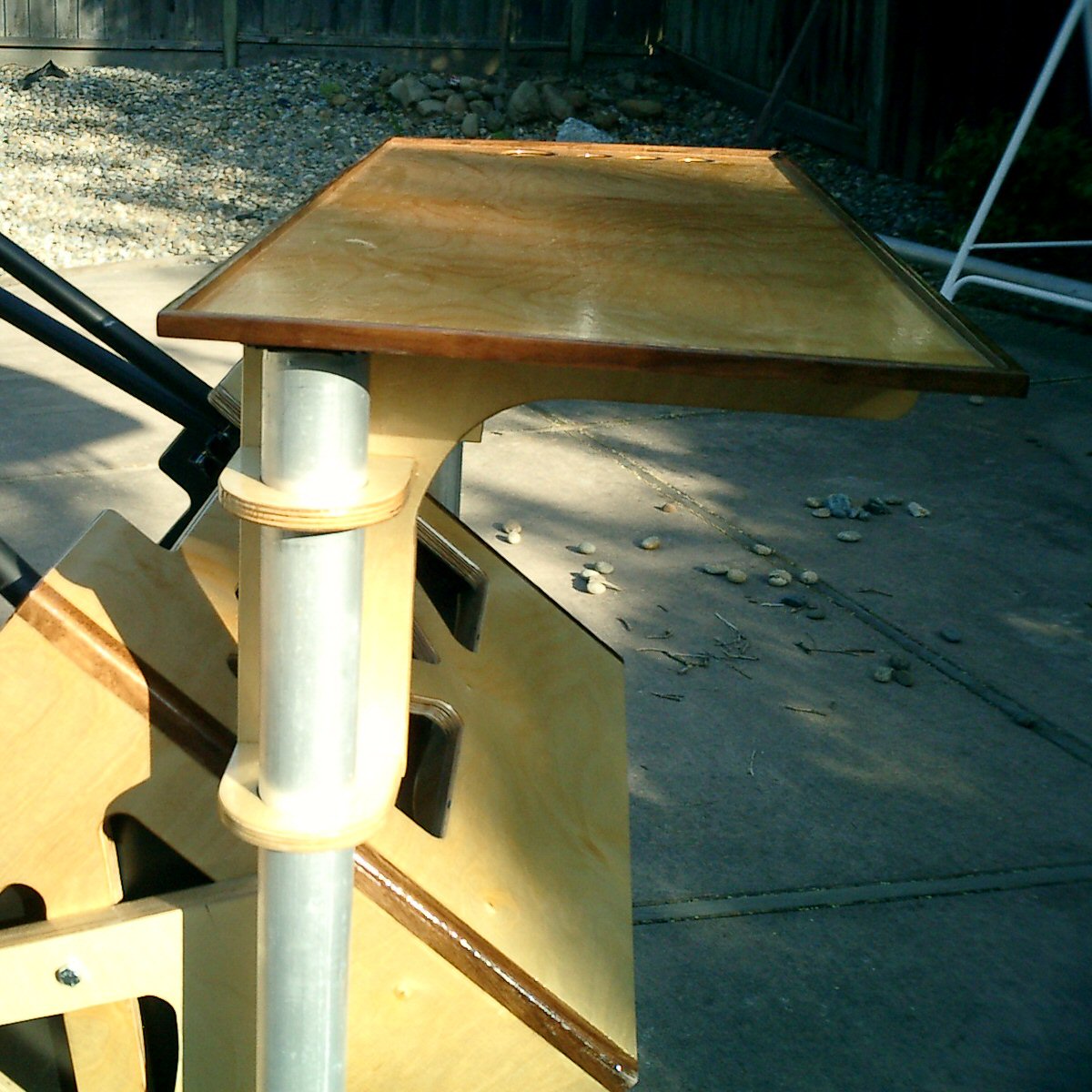
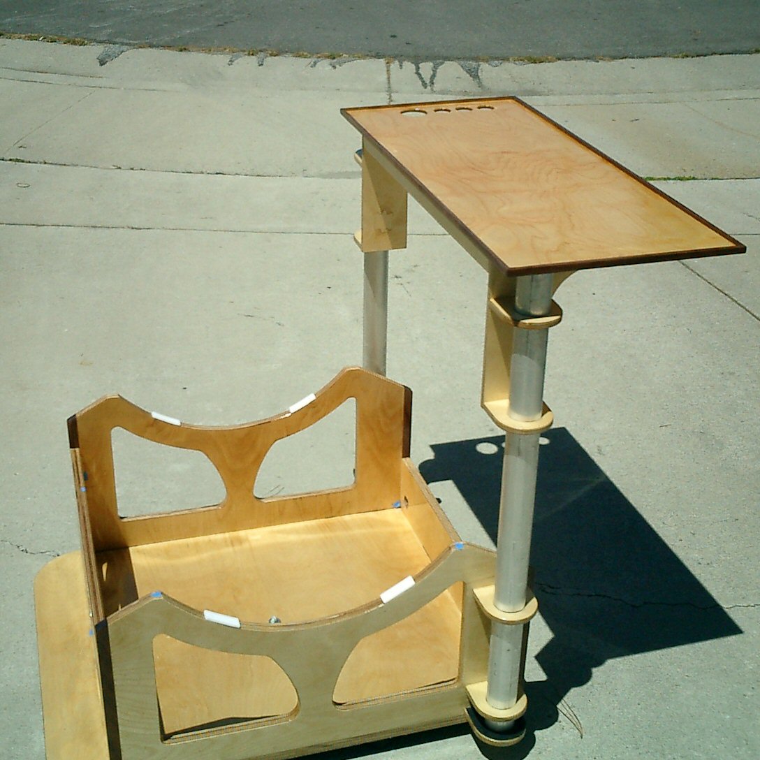
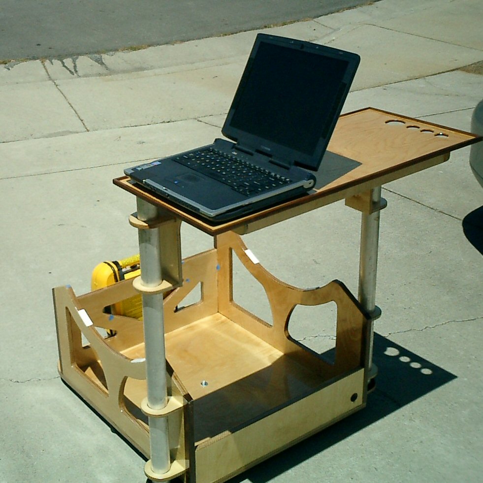
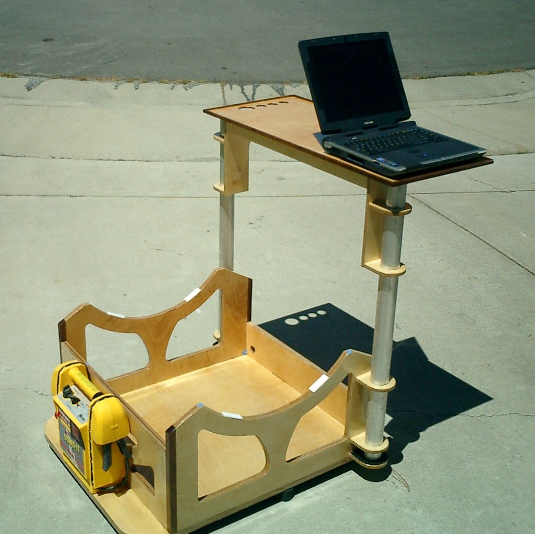
Laptop TableOne of my favorite parts of the design is the laptop table. I had already built and used a laptop stand on my Orion XT10 and had discovered the value of having the laptop at my fingertips, so I knew that I somehow wanted to support a laptop on the 18″. I thought about various designs and at some point remembered that I had a bunch of 2″ diameter aluminum tubing that I had purchased at a local recycling center during the early design of this telescope when I was thinking about making a 3 truss design. It was then a simple matter to come up with a support mechanism for the table. Assembly is very simple, I just slide the aluminum tubes into the lower supports and then slip the table over the top of the tubes. It takes seconds to accomplish. There was one gotcha that I would change if I were rebuilding the scope. I made the upper table supports be on the inside of the table. I couldn’t think of any reason this would be a problem since the distance between them was larger than the mirror box. What I had forgotten was to account for the altitude bearings attached to the outside of the mirror box. I had to increase the table height beyond my original table height so that the altitude bearings would clear the table supports. For future designs I would make the upper tube supports be towards the outside of the table.
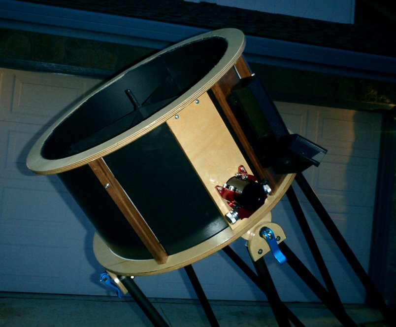
FansDuring the design of the mirror box I received the June 2004 issue of Sky and Telescope. It had an interesting article by Bryan Greer titled Improving the Thermal Properties of Newtonian Reflectors – Part 2, after reading the article I decided I should add support for both a front and rear fan to the design. Front FanI decided to place a fan on the mirror cover that would suck air away from the front surface of the mirror, while a fan below the mirror cell blew air onto the back of the mirror. I still wanted my mirror cover to offer some dust protection when the fan was not in use, so I came up with a small slide on the front of the mirror cover that allowed me to open or close the fan opening. I also added a small 12v jack onto the front baffle so I could easily supply power to the front fan.
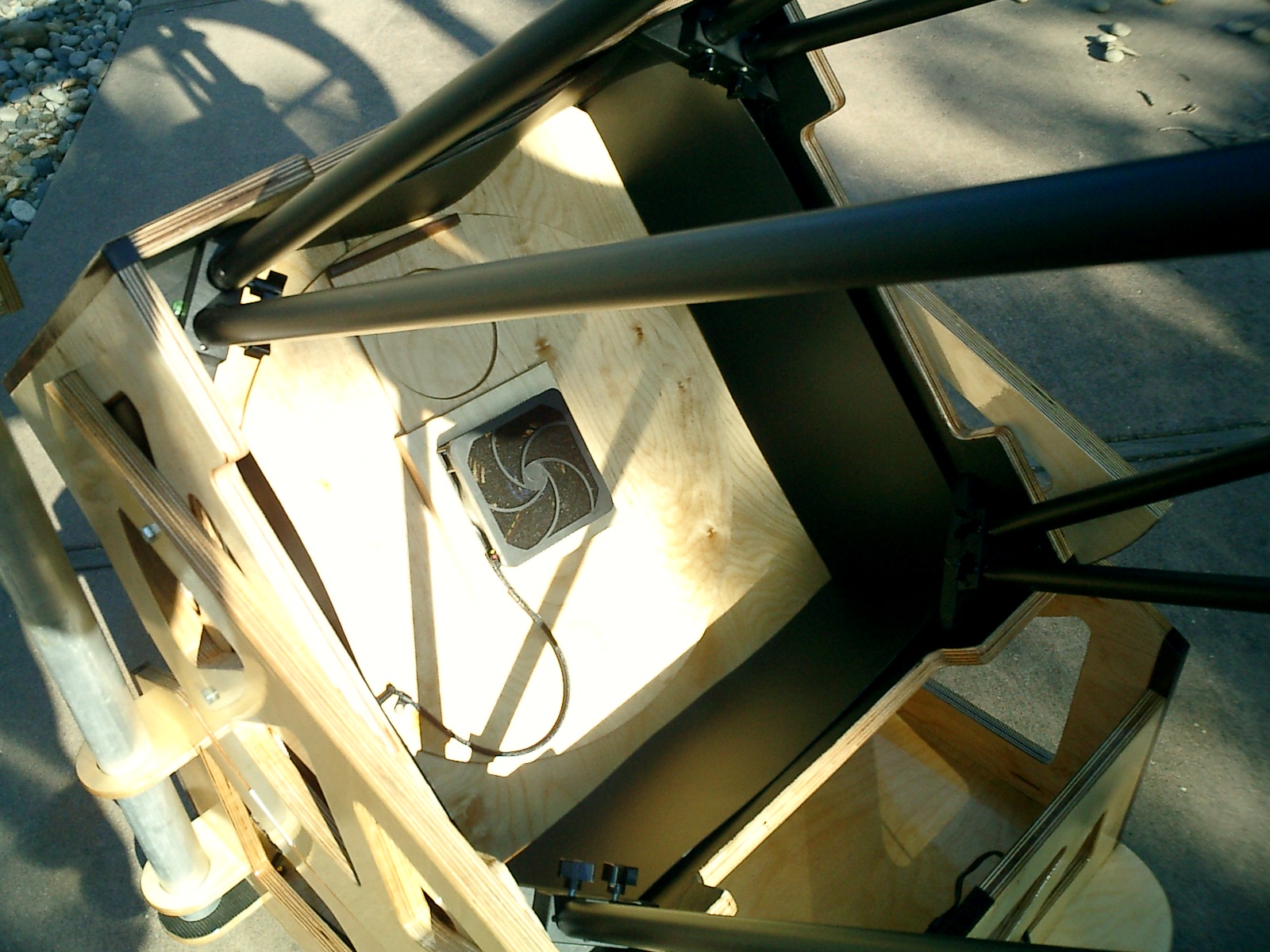
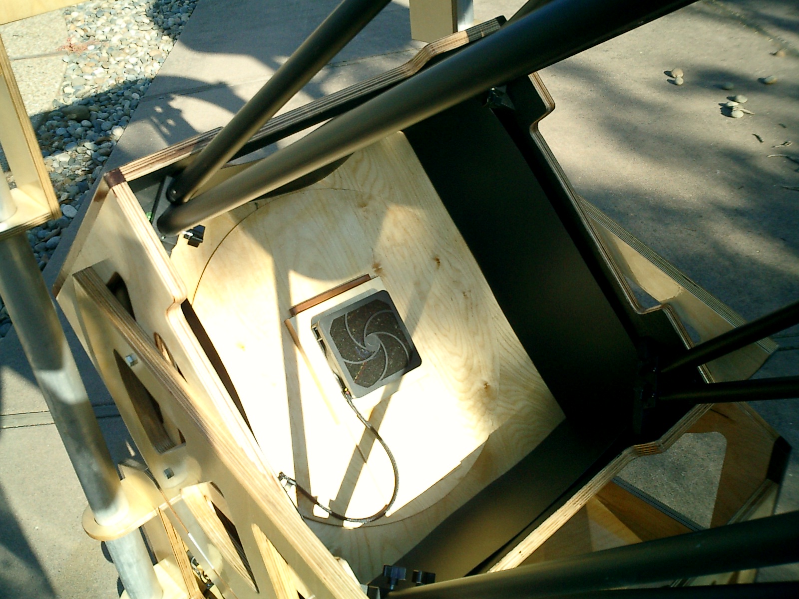
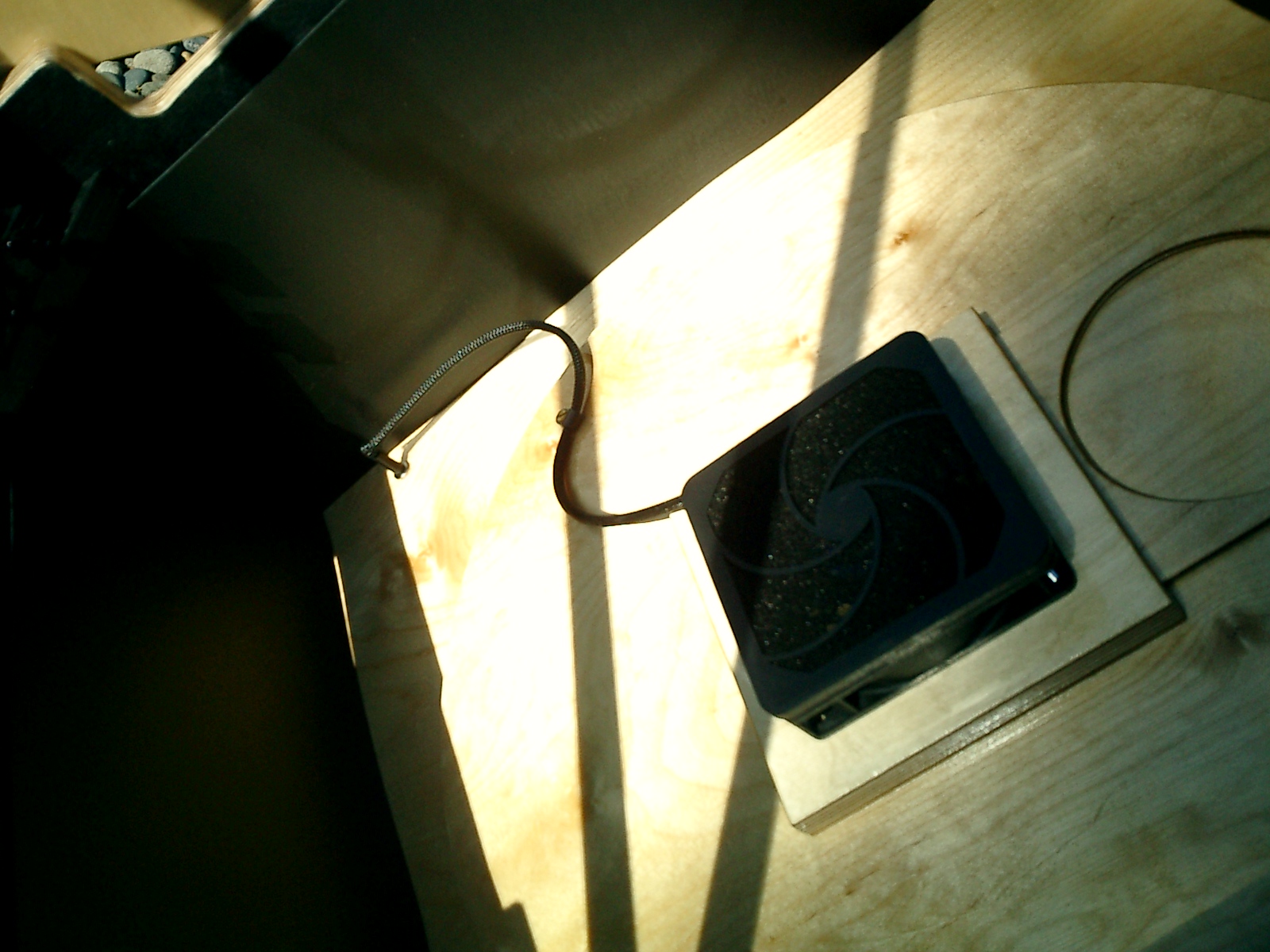
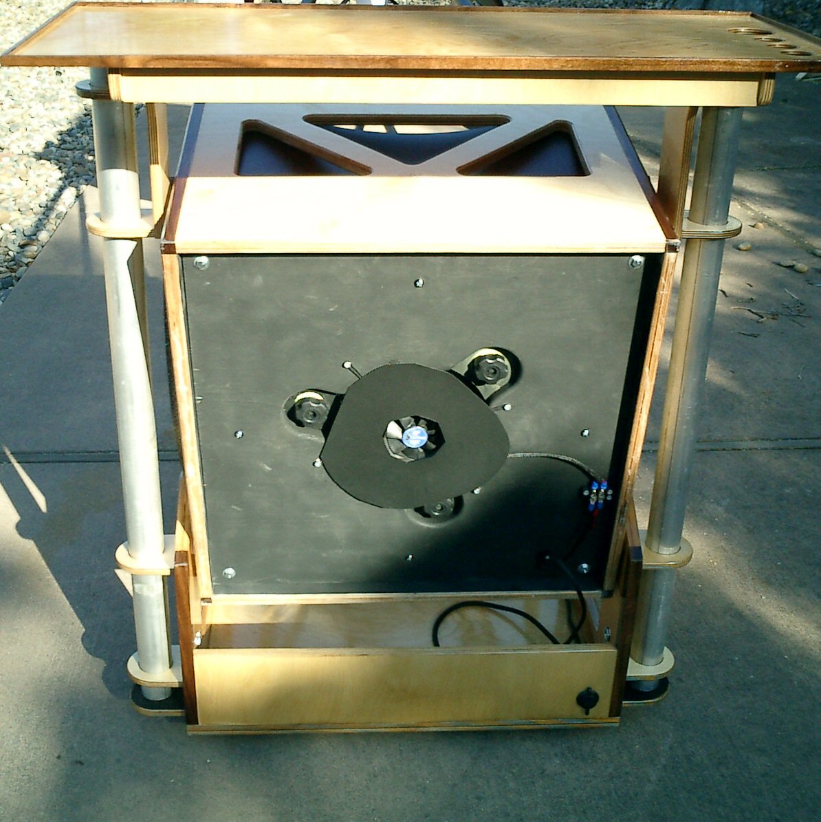
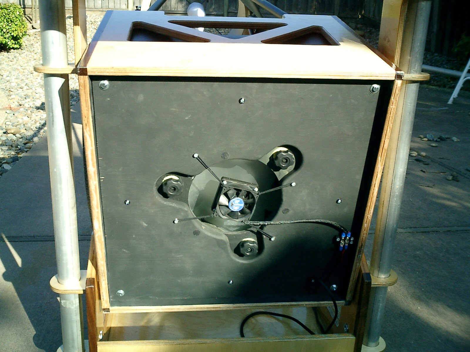
Rear FanThe rear fan is held in place by mini-bungee cords. Actually they are black elastic hair bands. This provides great vibration isolation for the rear fan. I have a piece of Kydex that I cut to cover the area around the fan so all of the air flow to the rear of the mirror is coming through the fan.
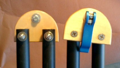
Truss Tubes and ConnectorsI am using 1″ thin wall aluminum tubing for my trusses. Due to a last minute problem with my lower truss connectors I at the last minute switched to the Moonlite Truss Connector system. It works very well. I modeled my upper truss connectors from the AstroSystems truss fasteners.They work so-so. I’m going to redesign them to work better. There are two problems. The first is that because there is a washer on the backside it is sometimes tricky to get the washer on the correct side of the connector on the UTA. Holding the UTA with one hand while trying to get the washer correct is not fun. The second problem is that there is a tendency for the connectors to rotate slightly which throws off the collimation. I can minimize this by making the clamps REALLY tight but they still occasionally slip. I’m thinking of adding sandpaper between the two connectors to see if that prevents the rotation. Otherwise I will redesign the connector so it can’t rotate.
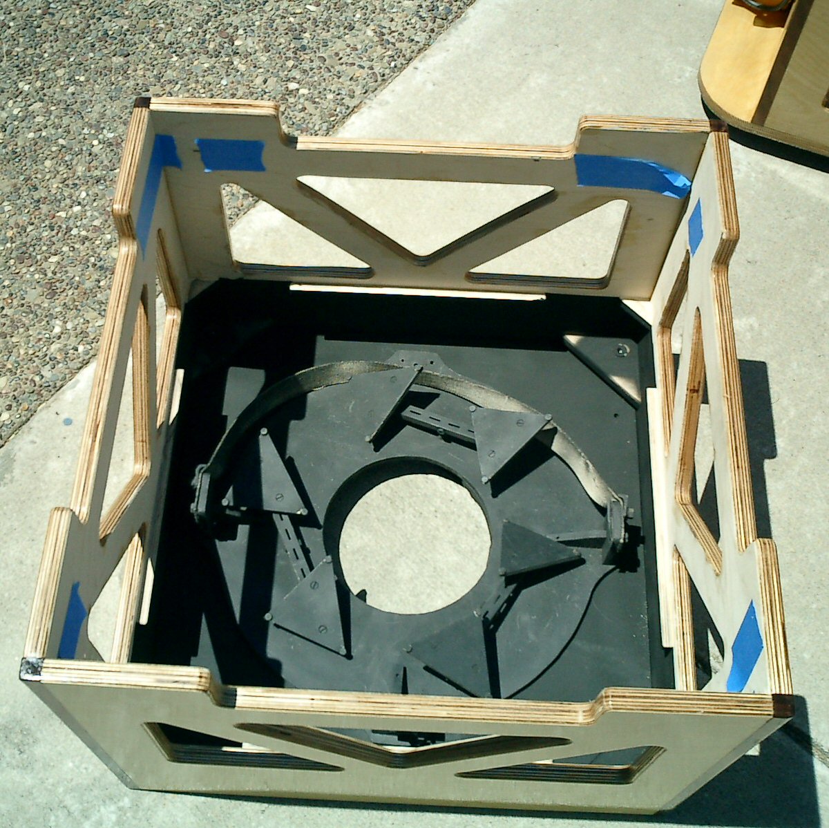
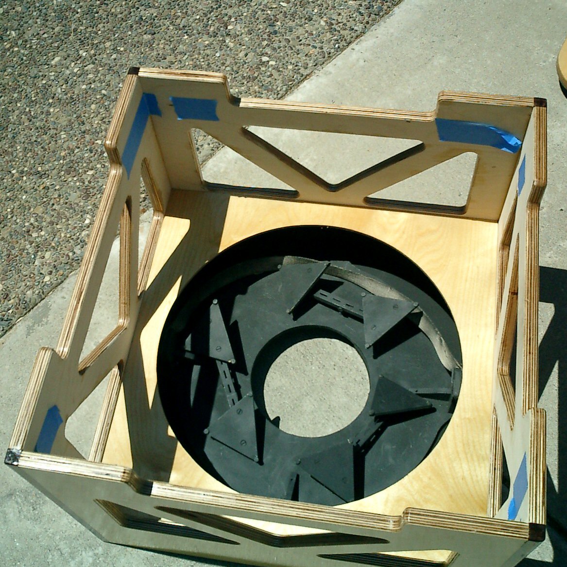
BafflingI lined the inside of the mirror box with Kydex to prevent stray light from entering through the cutouts I made to reduce weight in the mirror box. It’s visible in a couple of the images above. The first time I used the scope I noticed a little bit of stray light getting in from below the UTA. So I added a Kydex baffle to the lower part of the UTA to block this light. This can be seen in the picture of the UTA above. Electrical SystemI added electrical wiring to the rocker box and mirror box. This wiring consists of a cigarette lighter plug which plugs into the battery pack on the front shelf of the rocker box. This is then routed to a cigarette lighter socket mounted on the back of the rocker box. This is used to plug in the power supply for the laptop on the laptop table. In addition there is a connector that goes to the mirror box where 12v is supplied to both the front and rear fans.
|


Connect with me:

